
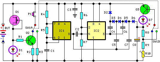
A Novel Experimental Technique for Use in Circuit Diagram The battery load tester circuit is a crucial tool for checking the health and capacity of batteries. However, like any other electronic circuit, it can encounter common issues that can affect its performance. One common issue that users may encounter is a faulty connection between the battery load tester and the battery. This can result in

The principle of the circuit as shown in block diagram Figure 1. When we bring the battery that requires test the voltage in this circuit. The circuit will get voltage to compare with voltage internal the circuit. Which come from the battery 9 volts, then display with LED, If the battery still has a lot of power.

How to Build a Battery Tester Circuit Diagram
Now we will build a circuit which can show whether the voltage that a battery is outputting is above or below a certain level. We can adjust the circuit so that any type of battery can be tested with this circuit. It would just require adjustment of the voltage. How we will build this circuit is mainly through the use of a voltage comparator IC.
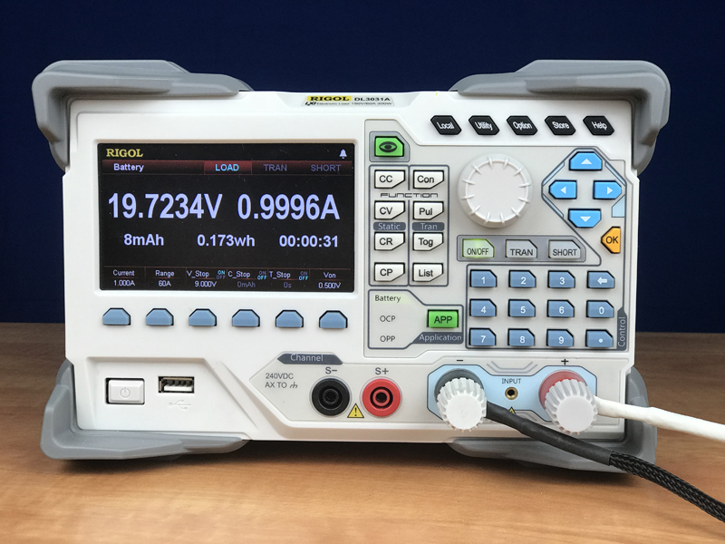
This Video is a demonstration of making and testing an Electronic load to test the Batteries and the Power Supply Units like AC to DC converter SMPS power su In principle, basic circuit of an electronic dc load contains an op-amp that drives a power MOSFET with a current sense resistor (sometimes called as load resistor). When the external voltage to be loaded is connected to the power MOSFET, and a control voltage is set by the multi-turn potentiometer in the circuit, the op-amp buffers this and
How to Make an Electronic Load Circuit Diagram
A quickly decreasing voltage indicates that the battery or batteries will have to be replaced soon. If a constant-current circuit is used for the load, the current can never too be large and there is no need to make an adjustment for the number of cells. The constant-current circuit is specially designed to work with a voltage as low as 0.9 V.
