Engineeringshock Electronics Circuit Diagram Hello guys, In this tutorial, I will show you how to make an RFID door lock access control system using Arduino. OK enjoy it now.Short and sweet tutorial.Onl
This video show my complete do it yourself RFID (Radio Frequency Identification) entry system from end to end. For more information and the schematic diagram

RFID door lock access control system Circuit Diagram
I have 2 RFID cards & 1 RFID tag/Keychain. The LCD display is used to show instructions to the user. I used a 12V solenoid lock to unlock the door. I make a detailed article on my website, you can visit my website for complete details of this project. Click to visit my Website:- "Techno-E-Solution" I already make a complete tutorial video on Finally, provide a 12V power supply to the solenoid lock. You can now test the system using the RFID tags. Ensure the system is powered up either through a USB cable connected to your computer or a separate 5V DC power supply for the Arduino Nano. Enjoy this project! A full video guide is provided below. We hope to see you in the next project.
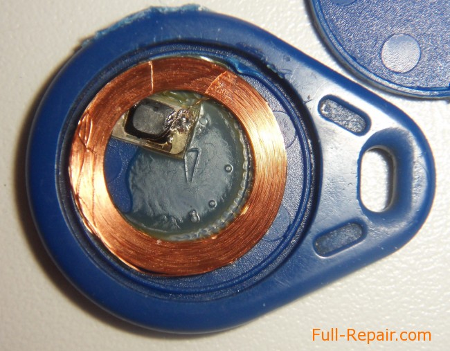
They're using PIC chips. They are similar to Arduino chips but the small differences make it impossible to easily copy code from one to the other. The low-power options on the chip are very important, particularly for the keyfob unit. If I had this wish, then I'd look at conventional RFID tags.
Arduino RFID 'Smart Door' Tutorial : 7 Steps Circuit Diagram
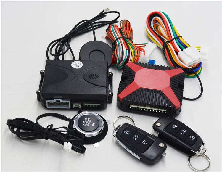
A few years ago I built a keyless entry system for my shop using a keypad, now it is time to update it to use an RFID key-fob. My homemade door actuator was made from parts out of an old VCR. The electronics controlling the system consist of a few components, a NE555IC (timer), a small NPN transistor, and a double poll double throw relay.

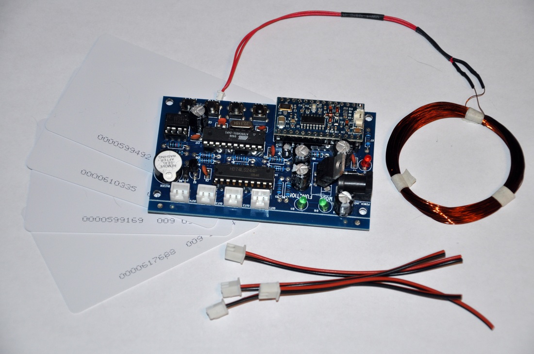
An RFID tagging system includes the tag itself, a read/write device, and a host system application for data collection, processing, and transmission. In simple words, RFID uses electromagnetic fields to transfer data over short distances. RFID is useful to identify people, to make transactions, etc. You can use an RFID system to open a door. This tutorial will show you how to use a ARDUINO with a RC522 RFID card reader to make a keyless entry door lock system..website : http://thezhut.com/?page_ Note down the RFID card UID, which later gets used in the code of the RFID Door lock system. Code for RFID Door Lock System using Arduino. This code is for an RFID door lock system using an Arduino. It reads the UID of the RFID card and compares it to a predefined authorized UID.