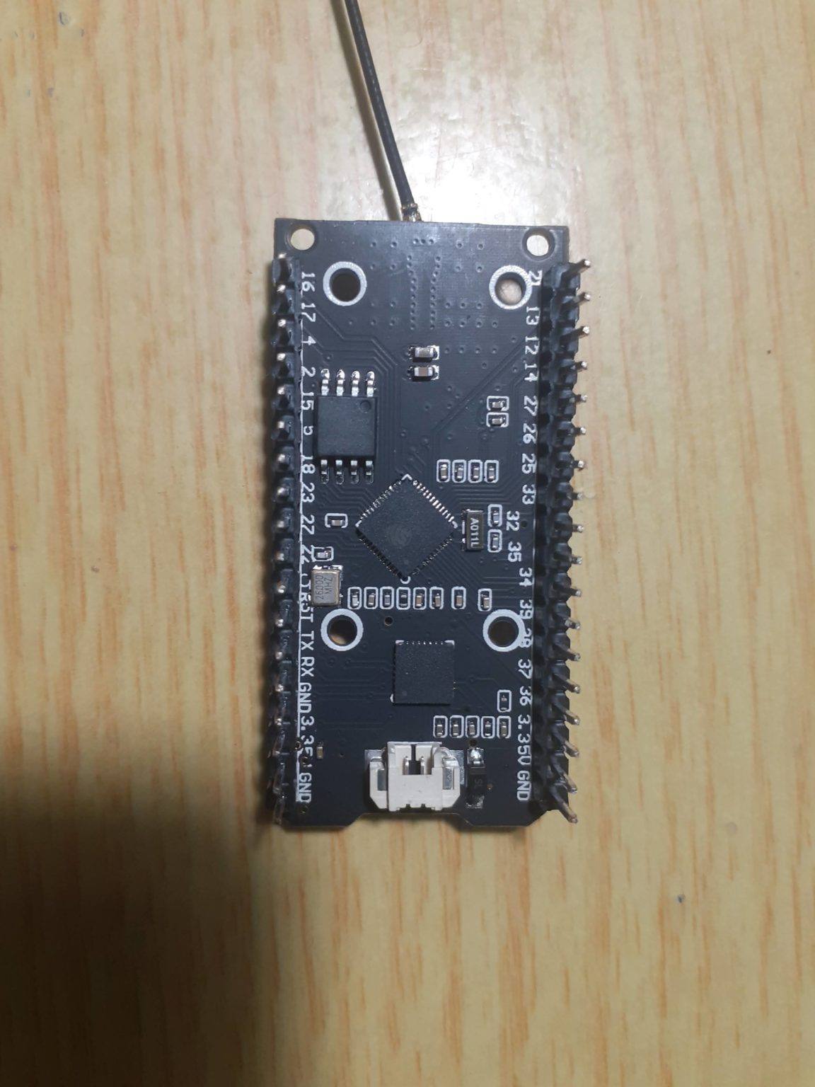
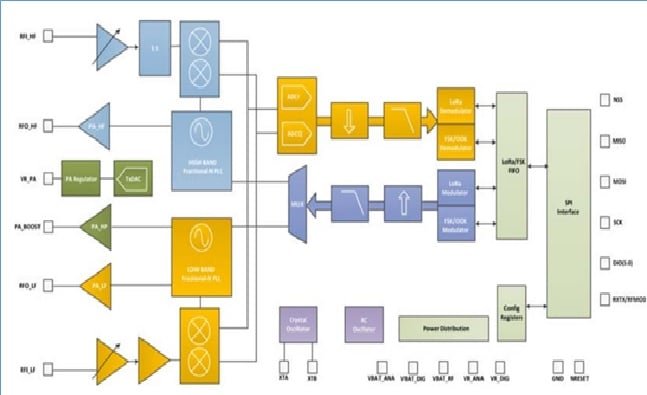
Lora Module Block Diagram To Make Pcb Design Circuit Diagram This circuit features an ESP32C3 Supermini microcontroller connected to a LORA_RA02 module and a DHT11 temperature and humidity sensor. The ESP32C3 handles communication with the LORA module via SPI (using GPIO05, GPIO06, GPIO10, and GPIO04 for MISO, MOSI, NSS, and SCK respectively) and GPIO01 and GPIO02 for additional control signals.
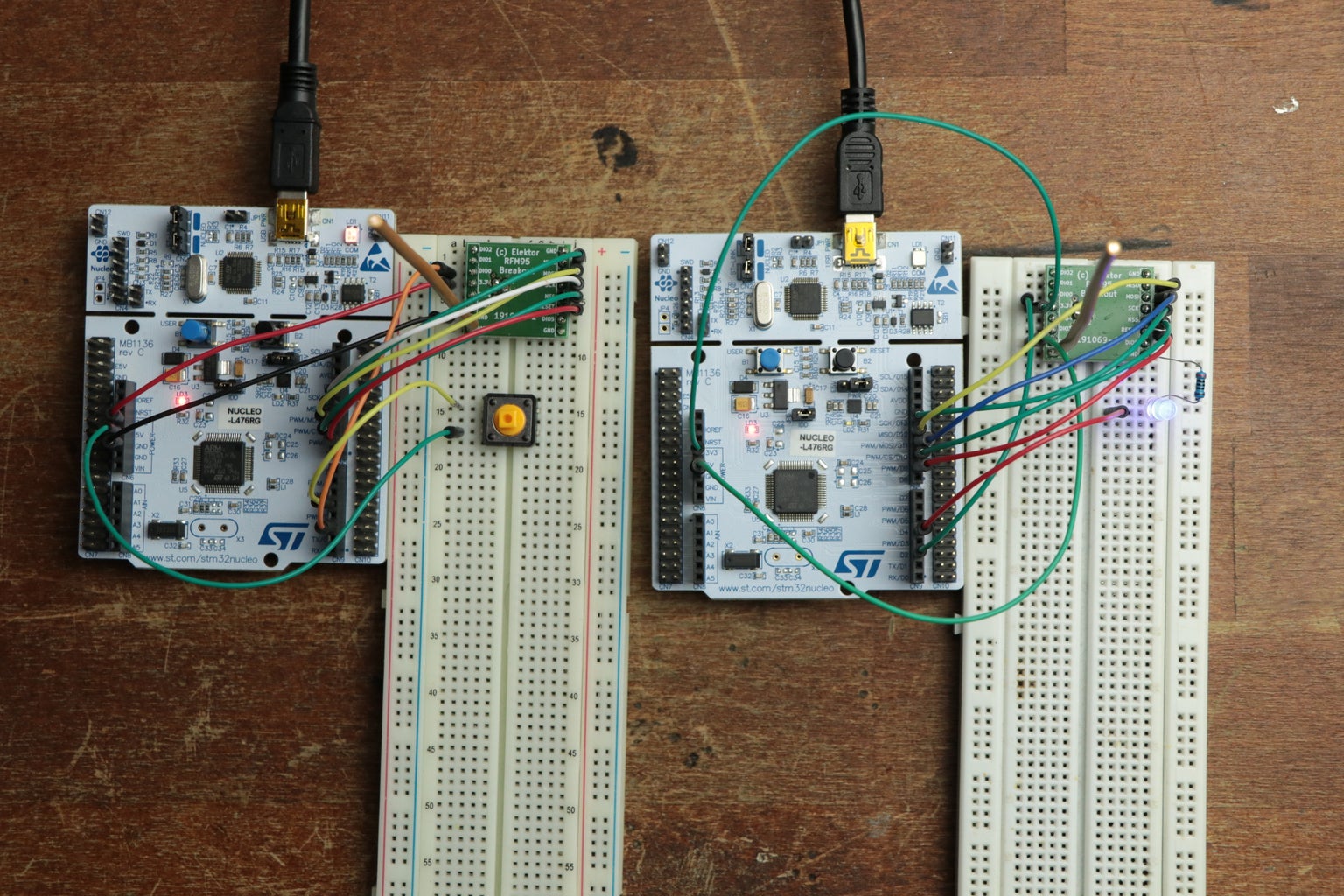
DIY LoRa System: In this project I will show you how to build a small LoRa transmitter and receiver with the help of STM32 development boards and RFM95 LoRa modules. Use them along with the reference pictures of my finished circuits in order to create your own. Step 4: Upload the Circuit! Here you can find the codes that I created for the

4 Points Of LoRa Antenna Design Circuit Diagram
Circuit Design of The ESP32 LoRa Project Example. The LoRa with ESP32 example project includes schematics and PCB for both the transmitter and receiver. With just a few components and straightforward programming, this example can be expanded into more complex systems—such as controlling multiple devices, integrating sensors, or even building
For the transmitting side we will use an Arduino UNO with our LoRa module. The circuit diagram to connect the Arduino UNO with LoRa is shown below . The LoRa module consists of 16 pins with 8 pins on each side. Out of these 16 pins, six are used by GPIO pins ranging from DIO0 to DIO5 and four are used by Ground pins. The module operates in 3.3V In the transmitter Lora circuit, we have connected the transmitter Lora module with Arduino Nano as per the circuit diagram. In the Transmitter Lora circuit, 5 push buttons are connected with Arduino digital pin D2, D3, D4, D5, D6. Whenever we press any push-button, the signal sent to receiving the Lora module to turn on or off the respective This circuit connects an Adafruit RFM9x LoRa Radio module to an Arduino MKR WiFi 1010 for wireless communication capabilities. The LoRa module's SPI interface (MOSI, MISO, SCK, CS) is connected to the corresponding SPI pins on the Arduino, allowing for serial data transfer between the devices.

02) LoRa Module with Arduino Circuit Diagram
This circuit integrates an ESP32 microcontroller with a LoRa Ra-02 SX1278 module for long-range wireless communication. The ESP32's digital pins are connected to the LoRa module's SPI interface (MOSI, MISO, SCK, NSS) and control lines (RST, DI00) to enable data transmission and reception.